RL03_Transmitter
Contents
- RL03 Main Page
- TX Board (and assembly)
- TX_SW and TX_PIR Board (and assembly)
- Power Use
- Adding Sensors
- Transmitted Packet Details
There are three transmitter boards the TX, TX_SW and TX_PIR
|
TX type transmitter board |
TX_SW and TX_PIR transmitter board. The difference is in the firmware |
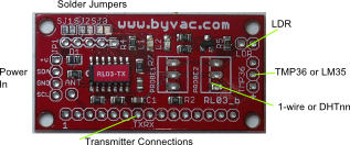
TX Board
This is a general purpose board and in fact it can be used as a receiver. It can take more sensors than the other board and is ideal for using with dual probes (boiler flow and return for example). Another advantage is that the power supply can be larger batteries for longer duration times, probably years.
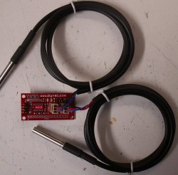
This is an example of two DS18S20 1-wire probes attached.
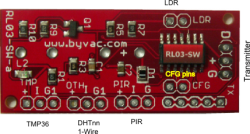
TX_SW & TX_PIR Boards
These boards have their own battery and holder so are self contained. They also can take a variety of sensors. The SW boards is designed to take a switch that will send a packet when the switch is either opened or closed. For example at the side of a door or window to detect if it is open. The TX_PIR is designed to take a PIR sensor and send a packet when the sensor is activated. The packet will contain how long the sensor has been activated.
In addition to the SW or PIR both can also read temperature, humidity and light levels, depending and what is connected to the board.
Power Use
The transmitter will send out a packet at 60 second intervals, give or take; each time a packet is sent the next packet takes a bit longer up to about 10 seconds. This is to reduce the collisions when using multiple transmitters as they all use the same frequency. The packet signal is sent to the TX pin and the actual transmitter, which ever one is used, is responsible for sending it over the air.
Power Timing
Between transmissions power is cut to all of the devices and the transmitter itself. Only the sleep power of the microcontroller is used during this period which is approximately 100uA. Power up time can vary depending an what is connected, the longest time is if a DHT11 or AM2303 is connected both require 2 seconds to initialise. The other devices are in the sub one second region. The power used for up time is about 3mA.
Adding Sensors
The transmitter can take several types of sensor and if possible will be automatically detected and reflected in the packet ID. The low nibble of the ID is set by the user* and the high nibble is set by whatever is connected to the transmitter.
| ID | Connected | Slot | Board | Note | Default ID |
| 0x10 | TMP36 | S2 | TX | Cannot detect this, assumes TMP36 | 16 |
| 0x20 | 1-Wire | S2 | TX | Detected | 32 |
| 0x30 | 2 x 1-wire | S2,S3 | TX | Detected | 48 |
| 0x40 | 1-Wire + PIR | S2,S3 | TX_PIR | 1-Wire detected PIR assumed. | 68 |
| 0x50 | TMP36 +PIR | S2,S3 | TX_PIR | Assumes TMP36 and PIR | 84 |
| 0x60 | DHTnn | S2,S3 | All | DHT Detected [1] | 60,64,62 |
| 0x70 | 1-Wire + SW | S2,S3 | TX_SW | 1-Wire detected SW assumed | 114 |
| 0x80 | TMP36 + SW | S2,S3 | TX_SW | Both assumed | 128 |
[1] When a DHT device is connected, this can be the DHT11, DHT22 or AM2303. This will give the temperature on S2 and the RH on S3. It applies to all boards and will override any other devices that may be connected. NOTE that the packet just contains the raw 16 bit data. It is up to the host to decode it.
In all cases the transmitter will send back 16bits representing each sensor, this may be an ADC value or a reading from the 1-Wire or DHT device. This enables the user to choose a decoding method.
LM35, TMP36 - Connect to TMP36 Input


These are both analogue sensors. Both have a 10mV per degree C change, however the TMP36 has a built in offset so that 0C is 0.5V, this makes it much easier to use with negative temperatures. The TMP36 input on the transmitter has a voltage reference of 1.024 (almost 1) and the output of the ADC is just over 1000. This makes it 1:1 so that a direct input of say 750 from the ADC converter can be read as 0.750mV (as near as makes no difference). If this were a reading from the TMP35 then the temperature would be:
750 - 500 = 25 degrees C
Wiring TX
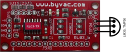
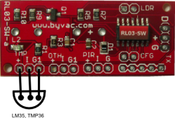
The ADC information is sent on S2
DS18B20 - Connect to DS18B20 input (max 2)


These are Dalas 1-Wire devices and are reasonably accurate as the information is digital. Usefully they can be purchased housed as a temperature probe as shown above. Two probes can be connected to the RL03. The RL03 will read the ROM code for each device and send separate temperature information on S2 and S3.
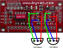
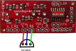
The transmitter will output a 16 bit value it is up to the host to decode those 16 bits.
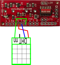
DHT11 and AM2302 - Connect to 1-Wire input (max 1)

")
The DHT11 and AM2302 both use the 1-Wire interface, however this is not the same as the Dallas 1-Wire but a special format to these devices. The RL03 can detect the difference. One device should be connected and it will send Temperature information on S2 and humidity information on S3.
The DHT11 is a poor relation to the DH22 (AM2302) and although they both output 16 bits the meaning for each is different. The DH11 just outputs a positive integer value for temperature and humidity whereas the DHT22 outputs a signed integer to 2 decimal places.
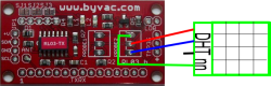
The transmitter will output a 16 bit value it is up to the host to decode those 16 bits.
PIR (Passive Infra-red)

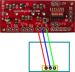
The TX_PIR type transmitter is designed to take a PIR that will detect movement. Because of the way it works the PIR pads are switched on all of the time. The time that the PIR is active (sensing movement) is recorded in S3 in mS.
NOTE: If the TX_PIR board is used without connecting a PIR which is perfectly reasonable for just detecting light levels and temperature then I and G must be shorted together.
Switch
The TX_SW board will detect the opening and closing of a switch and each time this happens will send out a packet. The switch uses the same pads as the PIR (marked PIR on the PCB)
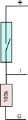
As an example this is how to connect a magnetic reed switch, the type used for door / window open detection. As the example above S3 will show 1 when the door is closed. For the other way round swap the position of the reed and resistor. A higher value of resistor may be used to reduce the current consumption. As it stands 100k will give 50uA when not active.
Packet Details
The packet consists of 6 values, ID is 8 bits the rest are 16 bits transmitted high byte first.
Packet: ID, S1(LDR), S2, S3, S4(battery), S5(age)
ID is described above
S1 (LDR): This is a direct value from the ADC converter on the transmitter. The reference voltage is 4.096V which must not be exceeded. The input to the ADC is on pin 1. There is a 47k resistor to ground on this pin, thus when connecting an LDR it forms a potential divider. Possible values are from 0 to 1023 (10 bit ADC). If an LDR is connected the brighter the light the higher the value.
This input can of course be used for other devices that output 0 to 2V.
S2 TMP36: The ADC conversion reference for this input is set to 1.024 volts and so if the TMP36 or LM35 device is connected to here then the host can make the conversion using the following information:
0 value is 0 volts
1023 value is 1.024 Volts
Any device can be connected to this input to read an analogue value. The voltage on this input must not exceed 1.024 volts otherwise the input will be damaged
S2/S3 DS18B20 in S3 or S3 is the 16 bit output of a 1-wire temperature device.
S2/S3 AM2302 or DHT11 Both of these devices give out two 16 bit values that occupy S3 and S4. No decoding is done so any of the DHT devices can be used.
S3 PIR When the PIR is activated by movement the time is is recorded in mS and when the movement stops the value is recorded in this value. The transmitter will update this value and send out a packet each time movement is detected. The packet is not sent until the movement stops.
S4, Battery Voltage: This is put out with every packet and is an ADC measure of the voltage multiplied by 100 to give 2 decimal places so a value of 513 is 5.13VS5, Packet Age: This is not sent by the transmitter but it is something that the receiver calculates when a packet is received.
x: When there is no device connected the result will be unpredictable.