BV4612B
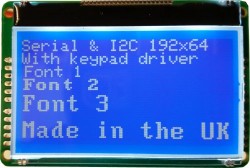
This is a user interface consisting of a 128x64 graphic lcd mounted on a controller PCB. It has a serial or I2C interface and also a keypad interface
The LCD screen has a protective coating which is not obvious, remove for a clearer display
- Data sheet
- I2C or Serial
- Images
- Arduino
- Raspberry Pi
- ByPic
- Dimensions
- FAQ & Tips
- EEPROM utility (python for the RPi)
- Purchase <Byvac Shop> <eBay shop>
Quick Start (Windows Serial)
The windows programs here are derived form Python and so any machine that runs Python will be able to run these, the Python source code has been provided.
- Connect to a serial port (TX to RX, RX to TX) *** ASSUME COM2
- Download Utilities (these are also in the image section)
- Unzip in a directory
- Open a command (cmd) window
bv4612Cmd com2 1 u // this will clear the screen
bv4612Cmd com2 1 "oHello Fred" // test to top line , quotes are needed
bv4612Cmd com2 2 b // gets number of keys in buffer assuming a keypad is connected
Tod display an image see the image tool page.
I2C or Serial
The device will work with both I2C or serial but only one at once. The mode is detected at start up. If there is no connection to an I2C but then the display will be in serial mode and this will be the default sign on screen.

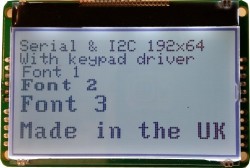
If there is an I2C connection then the device will detect the pull up resistors on the I2C bus and start with this screen.

Images
Images and special characters are formed using a paint program that must output 32 bit colour, even though only 2 colours are used. It is normal to use a black background and paint with white. It is important not to exceed the display size otherwise distortion will occur.
Some I2C masters can only output a limited number of bytes at a time and so although functions have been provided with Arduino and Python for I2C it is probably best to use the serial interface.
The display cannot handle BMP files directly and so they must be converted with a command line utility. for Linux and an exe file for Windows users:
More information about this tool.
Linux: python gUtil.py
Windows double click on the gUtil.exe, no need to install

This will only accept BMP files. The output can either be in decimal or hex format. The resulting output may need slight modification depending on the system used. For example a .h file for the Arduino may need the 'char' qualifier changing to uint8_t.
Arduino
- BV4612 Library and samples - version 1.05
The above zip file has a selection of examples and the library itself. NOTE this is for I2C, the Serial library is waiting for somebody else to write.
Keypad Section
void clrBuf(); Clears / resets the keypad buffer, the buffer is 79 bytes big
uint8_t keysBuf(); Returns the number of keys in the buffer
uint8_t key(); removes and returns the key in the buffer, if no key, returns a 0
uint8_t keyIn(uint8_t k); See if 'k' is in the buffer, 0 if not or a number representing its position in the buffer
uint8_t scan(); Returns the scan code if a pad is being touched, if no pad being touched then returns 0
void avg(uint16_t *b); Supply a buffer 8 integers big and this will return the 8 averages from each channel
void delta(uint16_t *b); Supply a buffer 8 integers big and this will return the delta value for each channel. The delta value is the difference between an average value and the touched value, if no pad is thouched the delaa value will therefore be 0
void EEreset(); Resets all EEPROM values back to their defaults
void sleep(); Shuts down device to save power, can only be awakened with a reset or I2C activity. NOTE the keypad will not respond when in sleep mode.
These functions are available but not applicable for this device.
EEPROM Section
NOTE: Values written to the EEPROM will not take effect until the device is reset. For what the values mean consult the data sheet in the Device Parameters section.
void trigger(uint16_t value); Write a new trigger value to the EEPROM
void hyst(uint8_t value); Writes a new hysteresis value to EEPROM
void keyPtr(uint8_t value); Writes a new key pointer value to EEPROM
void keySize(uint8_t value); Writes a new key table size value to EEPROM
void debounce(uint8_t value); Writes a new debounce value to EEPROM
void repeat(uint16_t value); Writes a new repeat key value to EEPROM
void timebase(uint8_t value); Writes a new timebase value to EEPROM
void defaultBL(uint8_t value); Writes a new default back light value to EEPROM
System Section
void EEwrite(uint8_t adr, uint8_t value); Writes a value to the specified EEPROM address
uint8_t EEread(uint8_t adr); Reads an EEPROM value at the specified address
uint16_t ID(); Gets the device id number as an integer, in this case 4242
void Version(uint8_t *b); Gets the firmware version as two bytes
LCD Section
void reset(); resets the display
cmd(uint8_t cmd); (31) Sends a command to the LCD controller; a command usually effects the way the display behaves.
data(uint8_t data); (32) Writes a byte to the display at the current cursor position. Note this is NOT a character but a byte see section 9 (LCD display in the data sheet).
puts(uint8_t *s); (33) Sends a string, the string must be terminates with 0, i.e. a valid C string
image(uint8_t *s, uint8_t row, uint8_t col); (compound); Sends a data stream to the LCD display given the starting row and column. The library uses I2C command 38 to send the image block by block. The image needs to be in the proper format as output by the image utility. There is an example in the library of how to send an image.
startMsg(); (35)This displays the sign on message that is stored in EEPROM.
bl(uint8_t v); (36) Turns the back light on (1) and off (0)
contrast(uint8_t m); (37) Sets the contrast, 20 is about right, can be set between 0 and 63.
dataLine(uint8_t *s, uint8_t row, uint8_t col, uint8_t nBytes); (38) This will send a sting of bytes to the display at the given position, remeber the bytes will appear as vertical lines. This command can be very useful for crating special characters.
font(uint8_t m); (40) Sets font 1 to 3.
clear(); (41) Clears screen and homes cursor.
column(uint8_t col); (42) Sets column position 0 to 127.
page(uint8_t row); (43) Sets page which is effectively the row, there are 8 rows, 0 to 7.
scroll(uint8_t s); (44) sets the scrolling line - experiment with this
write(uint8_t data); (45) This will write a single character using the current font to the display.
setCursor(int8_t col, int8_t row); (compound) Sets a new cursor position row 0 to 7, col 0 to 127
Getting Started
Use the device exactly as any other I2C device, wiring:
| Arduino | BV4242 |
| A5 | SCL |
| Ground | GND |
| A4 | SDA |
| 5V | V+ |
Although the display works on 3.3V it is okay to connect to 5V as there is an on board regulator. After connecting the Arduino, make sure the display is in I2C mode.
Unzip the library file and try one of the examples.
Raspberry Pi
Serial
Use the 3v3 supply
| RPi | BV4242 |
| GPIO TX | RX |
| Ground | GND |
| GPIO RX | TX |
| 3.3V output | 3V3 |
The serial port must be enabled, obviously, if not there are various web sites that show how this is done and also here and on this site here. The display should show that the Baud rate is 9600. any terminal emulator can be used, to check the connection is okay but the following Python code will do just as well.
Get the following 2 files:
wget http://www.byvac.com//downloads/Python/bv4612_s.py
wget http://www.byvac.com//downloads/Python/sv3clV2_3.py
Start Python
>>> import bv4612_s as b
>>> ui = b.BV4612S('/dev/ttyAMA0',9600,'j')
>>> ui.lcd('u') # clears display
>>> ui.lcd(ofred') # writes fred to the display
(press a couple of keys on the keypad)
>>> ui.keypad('c') # will get a key from the keypad buffer
The above is an example of how to use the class. The first character in the string, e.g. 'offred' 'o' is the command. See the data sheet for the list of commands. To send an image it must be converted into binary first using the conversion utility. If the image was called 32x32.bin then the command would be:
ui.image('32x32.bin',2,20) # sends image to row 2 column 20
I2C
Use the device exactly as any other I2C device, wiring:
| RPi | BV4242 |
| SCL | SCL |
| Ground | GND |
| A4 | SDA |
| 3.3V output | 3V3 |
The description here is for the I2C interface but the serial interface can also be used. When connection to the RPi make sure that the I2C start up screen is shown. I2c requires enabling if not already there are some instructions here.
pi@raspberrypi ~ $ i2cdetect -y -q 1 (NOTE the -q) 0 1 2 3 4 5 6 7 8 9 a b c d e f
00: -- -- -- -- -- -- -- -- -- -- -- -- --
10: -- -- -- -- -- -- -- -- -- -- -- -- -- -- -- --
20: -- -- -- -- -- -- -- -- -- -- -- -- -- -- -- --
30: -- -- -- -- -- 35 -- -- -- -- -- -- -- -- -- --
40: -- -- -- -- -- -- -- -- -- -- -- -- -- -- -- --
50: -- -- -- -- -- -- -- -- -- -- -- -- -- -- -- --
60: -- -- -- -- -- -- -- -- -- -- -- -- -- -- -- --
70: -- -- -- -- -- -- -- --
pi@raspberrypi ~ $
The address is 0x3d as shown. Just to get a feel of how it works i2ctools can be used:
- i2cset -y 1 0x35 41 // clears the LCD screen
- i2cset -y 1 0x35 45 65 // prints 'A' to the display
- i2cget -y 1 0x35 3 // gets a key from the keypad buffer (press a key and try again)
On the last command "i2cget -y 1 0x3d 3" if it returns 0, touch a key and send the command again, you will see that the key value will now be fetched.
LCD Utility
There is a utility that is already compiled called bv4612_lcd, this is entered at the command line with the following parameters:
bv4612_lcd <i2cAddress> <row> <column> "text"
The utility will also return any keys that are in the buffer, so touch the keypad a couple of times before sending. As an example to write "Hello" to the second line of the display
./bv4612 0x3d 2 1 "Hello"
Raspberry Pi BV4612.o Library
There is a C library very similar to the Arduino library and so will not be repeated here. It relies on WiriingPiI2C and so that will need installing. Once installed the supplied files can be compiled if required. To see how to use the library follow the bv4612_lcd or bv4612_tune examples.
gcc -lwiringPi -c -o bv4612.o bv4612.c // this will create a bv4612.o library
gcc -lwiringPi -o myProgram myProgram.c bv4612.o // this is to compile your own program
Python
There is also a python class that can be incorporated into Python programs.
wget http://www.byvac.com/downloads/py/bv4612/bv4612.py
The program does use notSMB and so that will also be required. As an example the following is a Python interactive session at the command line.
Python 2.7.3 (default, Mar 18 2014, 05:13:23)
[GCC 4.6.3] on linux2
Type "help", "copyright", "credits" or "license" for more information.
>>> import bv4612 as b
>>> ui = b.BV4612(0x35,1)
>>> ui.clear()
>>> ui.lcdPrint("Fred")
>>>
Images: These have only been implemented in Python. The class function is image("filename",row,col). Filename must be binary and is an output of the utility.
ByPic
Two drivers are available - for more information about ByPic see www.bypic.co.uk
http://www.byvac.com/downloads/BV4612/bv4612_i2c_driver.bas
http://www.byvac.com/downloads/BV4612/bv4612_serial_driver.bas
Dimensions
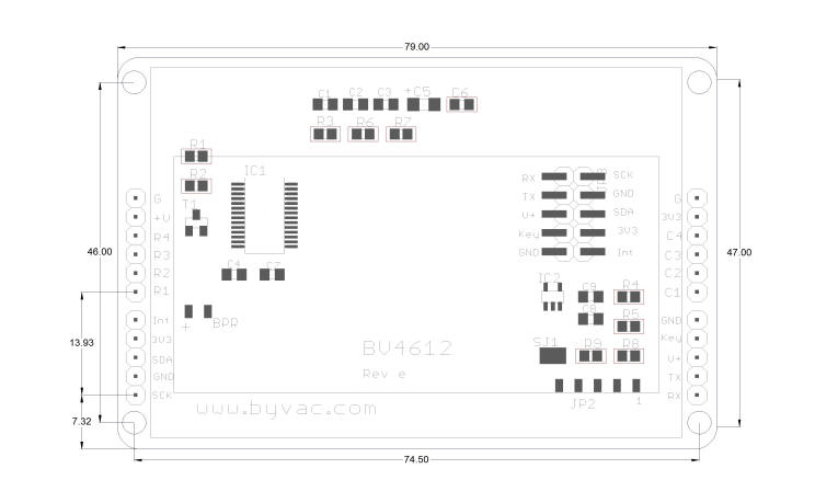
Use the dxf file for creating accurate overlays
FAQ
- I2C Swamp
The device is constantly monitoring the keypad but the I2C has priority over this and will always be acknowledged. If the host is constantly reading or writing to the device then it will have less time to do its job. If it is necessary to respond quickly to a key pad touch then use one of the interrupt pins rather than poling the I2C.
- Can't get display in I2C Mode
The device goes into the I2C mode when there is a pull up resistor on the SDA pin. If the device is not going into this mode then it means that the resistor is not there so check that the master device has them in place. It should then be obvious also that the SDA line needs connecting before or at the same time as power up.
- Image timeout is displayed when sending an image
This is because the host is sending the data too slow or much more likely insufficient data has been sent, if the device is expecting 50 bytes and only gets 49 then the timeout will occur when the device will be waiting for that last byte.