BV4115
Version 2 (BV4511_2) Blue label
Contents
Serial and Wi-Fi Relay Controller *** NOTE Version2 has blue label
Resources
- Data sheet
- Quick Start For wifi device
- Python code [1*] zip file containing bv4111 demo code and required files
- ESP Source code [2*] zip file
- BV4115 GUI
[1*] This code will work with Windows (providing python and pyserial is installed) and Unix. The only difference is the port selected in the initialisation function. This will also work on the Raspberry Pi. NOTE BV4111 code works for BV4115
[2*] This is the ESP8266 source code for the wi-fi link, Details.
Description
The relays controller is a serial (addressed, default 'd' (100)) device. Commands are sent and the relays respond. Commands include time delays so the relays can be turned on or off at a given delay. The wi-fi version is exactly the same as the serial version except that the serial connection is provided by wi-fi rather than the COM port.
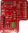
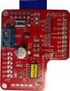
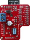
Hardware
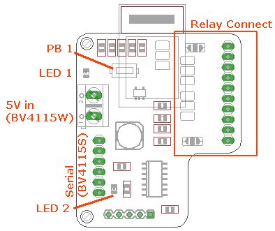
The relay connector is designed for 2,4 and 8 way relays and these can be selected by the various solder jumpers. Details of which are in the data sheet.
LED 1 is the power LED and LED 2 is the wi-fi configuration indicator.
Software Options
The BV4115 is effectively a serial device, the technique of using is to connect and then send a text command for example da1,1 will switch on relay 1. There are various methods of doing this via wifi.
** Make sure that you can ping the device first otherwise none of the techniques described below will work ** Also lets assume that your wifi router is 192.168.5.1, and you have set the BV4115 to station mode (1) 192.168.5.30 on port 80
Method 1
Open a command window and type
telnet 192.168.5.30 80
Now type
<enter><enter>+++info (<enter> is the enter or CR key on the keyboard)
This should bring up the ESP8266 details
Now type
<enter>+++rr
This will return with *A
da1,1<enter> (truns on relay 1)
Method 2
A more interactive method
- Download this file zip and extract
- Edit the text file 'wifiinfo' and put in the IP address on the top line and the port number on the next line down.
- double click on 'wifiRelay.exe'
Method 3
This is a command line utility, download the zip file extract and double click on the exe file. This can be used within batch files and the like.
Method 4
There is a GUI that can be downloaded from here, the text below explains how to use it.
Python
There is some demonstration code for this device written in Python. It will work on both Linux and Windows providing python and pyserial is installed. The code has been updated for firmware version 1.5 and so some parts will not work for previous versions. This is manly the discovery part that uses the new 'H' command.
Windows
Download and extract the zip files above. Place the extracted files in the same directory and open a command window, called a terminal in Linux. Connect the BV4111 to as serial device, BV101, BV104 or similar.
In the command window type
>>>python bv4111_demo.py COM2
This assumes that the serial device is COM2, the first two relays will click on and off.
Raspberry Pi
The device is connected to the RPi as follows:

The serial interface is connected to the BV4111 as shown with TX and RX crossed over. The BV4111 can operate from 3.3V and should do so in this case. The relays should be supplied from 5V, the Pi's 5V line may be able to supply this depending on how many relays are involved, although if the supply is directly from the USB then it should be able to handle it. The important point is that the BV4111 itself should be powered from the 3.3V supply.
*Important* Make sure the RPi is ready to accept serial information on those pins, this is described in the Connecting to Serial Devices guide
Software
The easiest way to get the code is to use wget on the Pi, do the following after connecting the BV4111 to the RPi
wget http://www.byvac.com/download/py/bv4111/sv3clV2_2.py
wget http://www.byvac,com/download/py/bv4111/BV4111.py
wget http://www.byvac.com/download/py/bv4111/bv4111_demo.py
python bv4111_demo.py "/dev/ttyAMA0"
Any problems see the Troubleshooting Guide on the RPi page.
Wi-Fi
This section deals specifically for working with wifi. See the quick start guide for details of how to configure the device to use on your network. Or see this page for more details.
For debugging and experimentation then use BVSerial, version 14 if using windows or version 11 if using Linux or the RPi. The windows version has an exe file so just double click on that.
Example

The IP address set for the example device is 192.168.11.30 and it is on port 80 so type into BVSerial at start up 'socket://192.168.11.30:80' This will connect to the wifi module, just as if it were a COM port. NOTE that .cr (dot cr) has been entered as the BV4115 requires CR at the end of each line.
In the example dV will return the BV4115 firmware version and dD returns the device ID (case is important). The device can be full controlled in this way. If a connection cannot be made then see troubleshooting at the bottom of this text.
For a more purposeful control a GUI is available

There is an associated file that goes with this called wifiinfo.txt, when the program starts it reads in the informationa and presents it to the side as 'Assigned to'
192.168.11.30
80
None
PC_W7
PC_XP
None
None
None
None
None
This is a copy of the file. It is useful as a reminder of what the relays may be connected to. The program is written in Python but has been made into an exe so that just double clicking on the exe will bring up the GUI as above.
Access to the Wi-Fi link
Most of the time any bytes going to the network socket (IP address and port) will be passed onto the relay controller. It is possible to access the wifi module directly without sending the command to the relay controller. This is done by sending a CR followed by +++. So for example to check that the wifi module is listening sending:
+++hello
Will return *A
To reset the relay controller the following is used
+++rr
The configuration of the wifi can also be done using these commands. A full list of commands is detailed above with the ESP firmware and Here.
Troubleshooting
1) Use the Quick Start guide to set the initial conditions for the ESP8266 wifi module. This will be done through the browser interface.
Lets assume that your wifi router is 192.168.5.1, and you have set the BV4115 to station mode (1) 192.168.5.30 on port 80
2) Open a command window and type ping 192.168.5.30. This is the first test, if everything is okay then you will get a reply, if not then press the button for longer than 6 seconds and follow the Quick Start instructions again. Some pointers:
- Make sure that the SSID and password match your home router exactly
- Make sure that the ESP8266 is in station mode
- Check the IP address and port number
3) In the command window type telnet 192.168.5.30 80
Now type
<enter><enter>+++info (<enter> is the enter or CR key on the keyboard)
This should bring up the ESP8266 details
Now type
<enter>+++rr
This will return with *A
Now type
da1,1<enter>
This will turn on relay 1
No response at start-up
The bv4115 consists of a wifi device and a microcontroller so there are two sets of commands. The microcontroler commands begin with 'd', e.g. dV and the wifi commands begin with +++.
Depending on the circumstances at switch on the BV4115 microcontroller part will require resetting with +++rr. After that everything will work fine. The reason why this command is not automatically sent by the software is because the relays would switch to the default state which is off and this may not always be desirable.
As an example suppose that the relays are connected to power a PC and the PC is switched on. When you contact(control) the relays with software you don't want the relays to switch off then on again by sending a reset as this would be bad for the PC. The use therefore is a one time +++rr reset when powering up and there after it stays switched on to control whatever is needed.
History
September 2015 Release
May 2016: Version 2 released for wifi operation using an HTML (REST type) API
June 2016: The yellow label version 1 is no longer available as it has been replaced by Version 2