BV107 Serial to Wifi
 |
 |
 |
|
| BV107_a Serial to Wifi | BV107_b | BV107 Breakout |
Introduction
The BV107 is a serial to WiFi (and visa-versa) converter. Similar to USB to Serial but WiFi instead of the USB. This means that any serial device can be controlled at a distance.
- BV107_a This is a Serial to WiFi board that operates on 3.3V
- BV107_b This is a Serial to WiFi board that will operate from 3.3V to 5V
- BV107 This is a break out board as well as a Serial to WiFi, all of the wifi pins are available
NOTE: This the firmware installed on the ESP8266 was inspired by the work done here.
Quick Start
In most circumstances the device will need to be set up as a station, similar to the WiFi on a laptop or tablet.
- This page shows how to do this
- There is also a quick start guide available in pdf.
There is more information on setting up using a serial connection later in the text.
The following settings are used in the examples: (assuming our router address is 192.168.11.50)
- Set the SSID (at the top of the browser) to the same name as your home router
- Set the password to your home router password
- Set the port to 23
- Set the gateway to 192.168.11.50
- Set the IP address to 192.168.11.? where ? is a number you choose [1]
- Set the Mode to 1
- Save & Reboot
[1] Make sure this address is not the same as any other address on the network.
The device is now ready for use, see the various modes for how to use it below.
Summary of Use

This is a typical set up for developing with and using a wired serial connection.

Arrangement when used as a station, the bridge replaces the USB to serial device.

Arrangement when used as an access point, the bridge replaces the USB to serial device.
The bridge is an almost direct replacement for the USB to Serial device, thus freeing the endpoint from wires. When using this arrangement instead of using a normal coms program such as mini term etc. the program also needs to be able to establish a TCP connection. Hyperterminal and putty will do this but a much easier option is to use BVSerial which can be set to connect to a specific socket (more later on sockets).
There are two possible options with this arrangement. The first and probably most common is to set the bridge so that it connects with an existing wi-fi access point (AP). To do this the SSID and password is needed for that AP and is set in the bridge (BV107). The advantage of this is that the bridge can be accessed anywhere the AP can reach and also any other device on the network also has access to the BV107.
An alternative is to set the bridge itself to be an access point, of course the client (the pc or smartphone) will need to connect to the bridge using the SSID of the bridge.
Hardware
There are at least three kinds of hardware that all work in exactly the same way, the difference is the features or number of pins. The break out board is used as an example as this has the most features.
BV107 Break out Board

BV107-A The board is supplied as a kit but with options. In minimal form it is as above with all of the SMD components mounted, pins and socket. The user can use either a Plug type or an SMD type module.


BV107-B As A but with the SMD type ESP8266 soldered in place, no 2x8 socket
PCB Details
The BV107 has an on board 3.3V regulator and a reservoir capacitor for transmission burst. All of the outputs are connected to pads for general purpose use. The pins are spaced so that it can plug into a breadboard.

Connectors

Serial: This is intended to be the main I/O for the device and would normally be connected to the equipment where the replacement serial interface would go. There is a GPIO4 output (that is only available on the SMD type ESP8266) which can be made to toggle low by sending a command from the TCP end. This is useful if a microcontroller is connected and it needs to be reset remotely.
I2C: This is connected to GPIO2 and GPIO14 (GPIO14 is only available on the SMD type ESP8266). suitable firmware is included in version 2c for the ESP8266 to operate this.
Programming: This is similar to the serial I/O in that UTXD=TX and URXD=RX however if DTR and RTS are connected to the designated pins a Python program can be used to program the ESP8266.
Power: The +V pin appears in three places and it is the input to the voltage regulator. This is rated as a maximum input of 6V and 300mA so a battery supply can be used.
Resistor
On this version of the board a resistor is needed for the CH_PD line. It has been left out as some applications need to control this line without a resistor in place. Future version will have a resistor as part of the PCB that can be removed if required. Under normal circumstances the CH_PD line needs to be high (3.3V) for correct operation. The resistor is provided but it must be installed by the user.


Position for when PHT type ESP8266 is used and for when SMD type is used.

Circuit click for larger image
USB to Wifi BV107_1 Boards


These are cut down version of the break out board. To program the ESP8266 use the serial interface but keep the button pressed down before connecting the power. See this page for detailed programming information

Circuit for the BV107_1, click for larger image
Usage Examples
** Versions with F1_1.9.15+ firmware can send and receive data directly from a browser.
192.168.11.5/hello // on the address bar
The serial will receive just the "hello" (assuming the device address is 192.168.11.5, port 80)
TCP End
Java Script
The device can be controlled from a browser in two ways, using the HTTP GET (or POST) and through web sockets.
HTTP Example
Click on the link or download the zip and run locally
http://www.byvac.com/downloads/BV107/httpType.html (zip of source)

This is a very simple example of how to send and receive using a web browser and a small amount of Java script. Some points to consider when using this method.
- The reply must be sent back by the device before the time out (set by +++restto)
- A connection is made each time the button is pressed and then disconnected either by timeout or by the client
- A disconnect can be immediately made by sending 0x1a back (^Z)
A web socket is a more permanent connection with the device, once connected data can eb sent back and forth until disconnected.
http://www.byvac.com/downloads/BV107/socketType.html (zip of source)

The source is a bit more complicated but it does give the opportunity of a two way communications and the other end can initiate the conversation. Because there is less set up (HTTP requires a connection each time) the communication can be a bit faster.
Browser Project
http://www.byvac.com/downloads/BV107/project.html (zip of source)
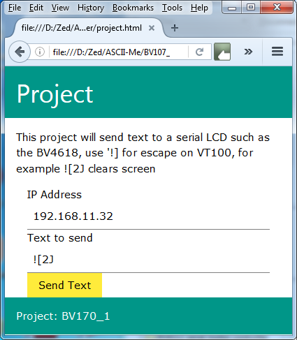
This will send text to a VT100 serial display such as the BV4618.
Serial End
NOTE: Using this method the ESP device is ALWAYS available regardless of the settings or IP address, the only thing that would stop communication is if the Baud rate is wrong. To correct this do a factory reset and it will be restored to 115200
As a station link. This is where the bridge connects to an existing AP (your home router). For this you will need:
- A USB to serial device to configure the BV107
- BVCOM2 or any general purpose terminal

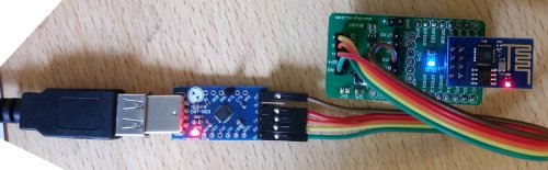
Connect the USB to serial as shown, note TX goes to RX and RX goes to TX. It is also useful to connect the DTR line which is on the programming connector but that is not essential.

At switch on you should see something like this. If the DTR line is connected then pressing the reset icon (next to the exit icon) will reset the ESP8266 and show TBREADY: again. If not then it must be fixed before proceeding any further.
The command set is now available, using the commands will enable any setup condition to be realised.
Testing
Assume the following set up for the ESP Device:
- IP address 192.168.11.30
- Port is 23
- Part of the home network (SSID, password set)
- Mode is 1
Keep the BVCOM and USB to serial connected as is. This will act as the terminal end. For a quick test use telnet, from a command prompt or simply type it in at the start button, thus(Windows 7):

Note that the same IP is used as was set in Step 4. A black window should open, anything typed on the back screen will appear on the serial BV_COM screen and vice-verse.
The BVSerial program can also be used, instead of specifying a com port, specify a socket as shown. On the same PC or another PC on the same network launch BVSerial and when asked for a com port type:
socket://192.168.11.50:23

You should now see that text types in at BVSerial will appear on BVCOM (BVSerial is line oriented so you need to press enter first)

Now type something on BV_COM2 and that will appear on BVSerial. NOTE that there is no echo on BV_COM2 by default.
Command List
See the details link on this page for the commands, including the I2C commands.
I2C
NOTE: There is an error on revision 0 (current revision) PCB in that the 3v3 pad is not connected to anything. It will need a wire soldering from that pad to a 3v3 connected pad.
Firmware
The firmware that is used on the ESP8266 to create a transparent bridge is open source. The zip file includes all of the source code. The firmware is in the firmware directory and has 2 binary files. Full details of how to upload new firmware is given in this link. You will need a USB to serial device.
The firmware is based on the work done by beckdac and the original can be found at the link. I have modified the commands mainly so that they work at the terminal and the TCP end. Also added I2C (with clock stretching).
Programming
If you just need to update the firmware then use this link, if you are more ambitious then follow the steps below. The latest firmware can be found in the ESP upgrade link given previously.
The BV107 has a connector that is designed for programming the ESP8266, a USB to serial device will be required. The following text will explain how to use the connector and thus program the ESP8266. You will need:
- Python version 2.7 with Pyserial
- This zip file.
The zip file contains the firmware and a python program that can download in 2 parts to the ESP8266. It does not work every time so perseverance is required.

Unzip the file into a directory, open a command window (start type cmd). Make sure you are in the same directory as the python file 'esptool.py' and type flash com10 (or whatever your com port is). You can see in the above screen shot it did not work the first time. Success is designated by two successful flash downloads, this takes about 30 seconds.
Factory Reset
To factory reset this device use the following:
- Power on the device
- Connect a wire from GPIO0 (RTS) to ground and hold it there for at least 10 seconds